[Safety]      [Quality Assurance]      [Inside Regenco]
archive copied from [http://regenco.mgi-servilink.net]
link back to Tasker's Web Notes for Toshiba's PSD  [West Allis] Facility


Low-speed balancing\
for rigid rotors...

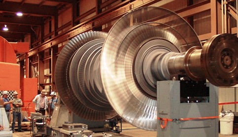
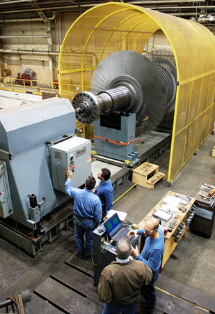
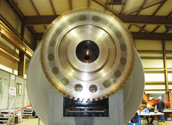
Rotating machinery in an unbalanced condition will result in unacceptable vibrations during operation. These vibrations lead to excessive wear and possible damage to the machine depending on the amount of unbalance and the duration of operation. For in-service rotors, unbalance can be caused by loss or change of mass due to damage, wear, or deposits. Turbine spindles are the most likely candidates for a low speed balance depending on their flexibility. Due to their larger relative stiffness and large diameters, low pressure (LP) spindles are especially well-suited for a low speed balance.

Dynamic Balancing &
Overspeed Facility

High-Speed
IRotor Balance

Low-Speed
Rotor Balance

Goals and conditions for low-speed balancing.

The goal of all balancing, low- or high-speed, is to minimize residual unbalance by shifting the center of mass to the axis of rotation. Balancing is carried out with respect to the axis of rotation as defined by the centerline through two or more journals.

  • Best application is to rigid rotors
  • Balancing is carried out in two or three planes
  • Addresses translation and couple (rocking) rigid body modes
  • Low speed rigid body forces and moments are compensated by balancing
  • Does not resolve inner moments that can only be observed at high speed due to the centrifugal force effects of local mass eccentricities

The severity of local mass eccentricities across a rotor is evaluated from run out measurements carried out on the rotor. The measurements are a means to assess the degree of mechanical unbalance and applicability of low-speed balancing for a particular rotor.

Reference Paper
When to
Low Speed Balance