[Tasker] Woodward 505 LST [Tech Support Index]
Woodward 505 LST
Speed Droop Deadband
Written 7/2012 / Updated 11/2012
Purpose
Updated 11/2012
Purpose/Industry Need:
http://www.nerc.com/filez/standards/Frequency_Response.html
Frequency Response, a measure of an Interconnection’s ability to stabilize
frequency immediately following the sudden loss of generation or load, is a
critical component to the reliable operation of the bulk power system,
particularly during disturbances and restoration. Failure to maintain frequency
can disrupt the operation of equipment and initiate disconnection of power plant
equipment to prevent them from being damaged, which could lead to wide-spread
blackouts. There is evidence of continuing decline in Frequency Response in the
three Interconnections over the past 10 years, but no confirmed reason for the
apparent decline. The proposed standard would set a minimum Frequency Response
obligation for each Balancing Authority, provide a uniform calculation of
Frequency Response and Frequency Bias Settings that transition to values closer
to natural Frequency Response, and encourage coordinated AGC operation.
See also: NERC Standard BAL-003-1 and Attachment A
The purpose of speed droop while operating in Valve Position Control is to contribute to the grid frequency stabilization by increasing or decreasing valve position if the grid frequency deviates outside a prescribed deadband. Frequency stabilization participation is bi-directional, but most often is needed when a large generating source drops off line unexpectedly causing the grid frequency to sag. The grid frequency could climb if connection to a large outgoing transmission line were to open, but that is less common than loss of generation. The NERC (North American Electric Reliability Corporation (http://www.nerc.com) deadband expectation is 36 mHz (±2.16 RPM) or lower. Old legacy hydro-mechanical governor systems typically have droop built into them without configurable deadband, so they are always operating in Speed Droop Mode. Some newer computerized governor systems have the ability to operate in Valve Position Control Mode rather than Speed Control Mode once the generator breaker is closed. If a governor system is able to operate in Valve Position Control (VPC) mode, the governor system will typically provide configurable speed droop deadband functionality to enable grid frequency stabilization participation.
The Woodward 505 LST Governor for Large Steam Turbines can be configured to operate in Valve Position Control (VPC) once the breaker is closed. The 505 LST governor has a configurable speed droop deadband. The value of the speed droop is also configurable. Speed droop is typically configured to 5% of rated speed, meaning that if the speed deviates 5% from the speed setpoint (60 Hz) the throttle will fully open or close, so lowering the speed droop value will cause the valve to move more for a given frequency deviation, thus increasing frequency participation response as the speed droop is lowered. 5% speed droop has been the de-facto industry standard for many years, but the value can be lowered if more response is desired. Lowering the configured speed droop value will result in more throttle response, but less stability. Increasing the configured speed droop value will result in less throttle response to frequency deviations, but more stability.
The NERC Standard BAL-003-1 is looking for the Balancing Authority to document performance in MW of response per 0.1 Hz or MW/0.1Hz
For fast grid frequency transients, the primary stabilization participation functionality is pushed down to the governor level because throttle response is almost immediate (response within seconds), however, utilizing droop to control throttle position is proportional control only. The integration portion of the PID loop is provided by a central controller (ACG / Automatic Generator Control) that monitors frequency and sends a load demand signal or raise and lower signals to the individual units that are on-line. ACG Integration is considered Secondary Control with a PID loop integration time in minutes.
A central grid controller is working to maintain grid frequency and local voltage. There is a direct relationship between voltage and power such that changing voltage will change the power and effect the frequency, however, primary frequency control is assigned to the individual unit governors. Frequency control is performed independent of the voltage even though voltage variations will impact speed. Voltage and reactive load vary with location on the grid so voltage and reactive current control is localized and distributed. Grid frequency does not vary with location. There may be some phase shift due to reactance, but all synchronous units on the same grid are hard locked to each other in frequency, so it is logically sensible to have the integral function of the frequency control PID loop centralized. The central grid frequency controller will send a load demand signal or raise and lower pulses to the individual generator unit governors to maintain frequency. Localized voltage and reactive current control is an independent function that will react to maintain local voltage and reactive flow.
Voltage is controlled by numerous distributed devices, sourcing or sinking reactive current, including the generators which can vary their reactive current participation. The individual generator reactive current is a function of the generator field excitation controller rather than the speed governor. Unlike the hard frequency lock, a synchronous generator has an elastic voltage lock to the bus. Utility generators are coupled to the grid through transformers which have losses so varying the generator reactive current will equate to a small change in voltage on the generator side of the step up transformers.
As previously noted, voltage changes will influence grid frequency, but the voltage controller is not used to control frequency. The primary proportional frequency control is pushed down to the individual governors operating in speed droop, and the integral part of the grid frequency PID loop is handled by a central controller (AGC). Generator units with older controls typically receive raise or lower pulses from the central controller to change their individual governor speed setpoints or throttle position. Units with newer more capable controls often receive a load demand signal from the central frequency controller.
There are some control loop speed issues. If the grid frequency deviates, the governor speed droop will try to open or close the throttle and provide more or less load as a proportional response to the change in the controlled variable, however, if the units DCS is operating in load control, it will see the change in load and begin to counteract the proportional speed droop response. The governor speed droop response will typically be tuned much faster than the DCS load controller, so the governor speed droop should be effective, however, as DCS control loops improve, enabling the individual load PID loop speeds to increase, the effect of the local unit DCS load controller counteracting the speed PID could become an issue. The other part of the control loop speed equations is how fast the central controller (ACG) responds to the grid frequency change. The central controller should integrate and send the individual units raise or lower signals. If the central frequency controller integration is slow, then the individual unit load controllers will have more time to counteract the speed droop proportional correction.
The NERC Standard BAL-003-1 discourages response withdrawal through secondary control systems. Response withdrawal will occur if a unit DCS is configured for load control and the load control loop is tuned fast.
See Also, the Woodward 505 LST Manual Page (PDF) describing the Speed Droop Deadband.
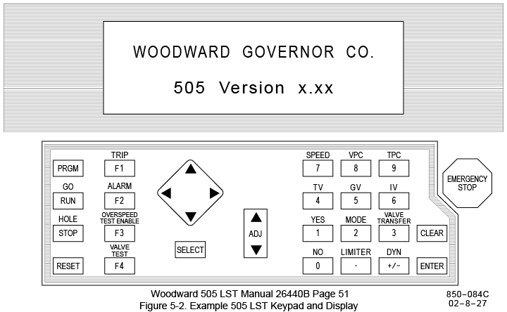
The Woodward 505 LST Modbus Speed Droop Deadband Values are not configurable in either the Configuration Program Mode or the Service Mode. The Values can be changed in the Debug Mode. The Debug Mode includes tunable values that are not intended to be utilized by the average end user, however, a few of the configurable values that various end users may need to modify are accessed via the Debug Mode. The Debug Mode interface is more cryptic and less intuitive than the more thoroughly documented Program Mode or Service Mode.
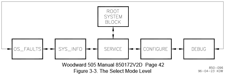
Refer to the [Generic
505 Debug Mode Overview] for instructions on entering the Debug Mode
and the Figures below illustrating the navigation arrangement
The 505 LST has 2 tunable fields for the Speed Droop Deadband, a Low and a
High value bracketing the synch speed.
The Tunable Fields for the Speed Droop Deadband are:
Low Limit Field: FREQ_LMT.IN_LOW is defaulted to 3597
RPM ~ 50 mHz below synch speed
Upper Limit Field: FREQ_LMT.IN_HIGH is defaulted to 3603 RPM ~
50 mHz above synch speed
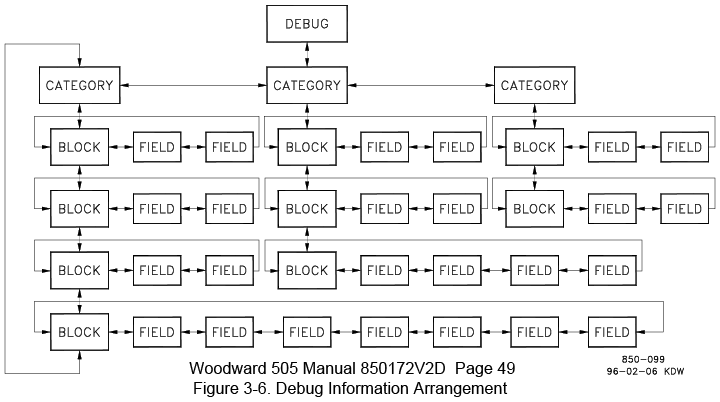
Both of the Fields are reached by moving laterally with the Diamond
Navigation Key from within the
"FREQ_LMT.A_LIMIT" Block which is nested in the "VPC" Category
Deadband Values
Updated 11/2012
The Woodward Default values of ±3 RPM ~ ±50 mHz, match the old NERC
value, however, sometime around or before 2012, the NERC values for Speed Droop
Deadband were tightened. The revised NERC
expectation is now ±36 mHz (±2.16 RPM) or tighter.
To comply with the NERC expectation, Tasker recommends setting the Speed Droop
Deadband to ±2.1 RPM ~ 35 mHz.
The Woodward 505 LST deadband parameter resolution is only 1 decimal place, so
36 mHz is not achievable exactly
Low Limit Field: FREQ_LMT.IN_LOW 3597.9 RPM ~ 35 mHz
below synch speed
Upper Limit Field: FREQ_LMT.IN_HIGH is defaulted to 3602.1 RPM ~ 35 mHz above
synch speed
Tightening the deadband further will cause frequency participation to occur sooner, but too much tightening defeats to purpose of deadband and may result in some instability which could accelerate valve rack wear issues.
In addition to the configurable deadband values, the magnitude of frequency
participation can also be adjusted by varying the droop setting.
Droop is set at 5% by default, the de-facto industry standard.
Decreasing the droop value will increase the magnitude of frequency
participation, but decrease stability.
5% droop is recommended. The 505 LST adjustment range is 0 to 10%.
Values below 2% are not recommended.
The 505 LST Speed Droop Deadband is adjusted in the Debug Mode which is
accessible with the unit on-line
The 505 LST Speed Droop value is adjusted in the Program Configuration mode.
The unit must be shutdown to change values in this mode.
Instructions / Specific the 505 LST Modbus Speed Droop Deadband
Written 7/2012 / Updated 11/2012
[Tasker] Woodward 505 LST [Tech Support Index]
Woodward 505 LST
Speed Droop Deadband
Tech Support Email Chain between Tasker and Woodward / in reverse chronological order
Updated 7/2012
From: Turbine HelpDesk [mailto:TurbineHelpDesk@woodward.com]
Sent: Thursday, July 19, 2012 12:18 PM
To: Tom Truax
Cc: Turbine HelpDesk
Subject: RE: 505 LST Speed Droop Deadband Question?
Importance: High
One more note. In Debug mode, using the adjust key will adjust the number by a
certain percentage. This percentage is actually quite large for the change you
want to make so especially if you are messing with it while the unit is online,
I would NOT use the ADJ key! So when you’re looking at the tunable, I would
recommend pressing ENTER, typing the number, and then press ENTER to put in the
change…
-Walter
From: Turbine HelpDesk [mailto:TurbineHelpDesk@woodward.com]
Sent: Thursday, July 19, 2012 12:09 PM
To: Tom Truax; Turbine HelpDesk
Subject: RE: 505 LST Speed Droop Deadband Question?
Hi Tom,
Are you familiar with Debug mode? It’s the same on the LST as any other 505 that
is in the actual 505 hardware. The deadband is simply put in as a high and low
limit, in RPM. In Debug Mode, go to the “VPC” category and then the “FREQ_LMT”
block name. The dead band is set by the tunables on this block. You will have to
set both the high and the low limits to the desired speed setting. The field
names are “IN_LOW” and “IN_HI”, which are by default ‘*3597’ and ‘*3603’
respectively.
Best regards,
Walter Grassens - Application Engineer - Turbine Engineering Services - Woodward
From: Tom Truax [mailto:tdtruax@tasker.us]
Sent: Tuesday, July 17, 2012 23:36
To: Turbine HelpDesk
Cc: 'JMRuplinger@wisconsinpublicservice.com'; 'JMBudde@wisconsinpublicservice.com'
Subject: 505 LST Speed Droop Deadband Question?
Attachment: 26440b_droop_notes_print.pdf
Woodward Turbine Help Desk,
Not sure who you have currently supporting the 505 LST, so I’m submitting my
support request to the Turbine Help Desk for initial review.
My end use Customer, Wisconsin Public Service, has a question about the 505 LST
Speed Droop Dead Band. Specifically, is it possible to change the deadband value
from its default of ±3 RPM (±0.05 Hz @ 3600 RPM) to something lower? There is no
provision to change it in either the Program Configure Mode or the Service Mode,
but I suspect that it may be changeable in some other menu.
WPS has 3 operational 505 LST's in service plus a spare. They would like to
tighten up the 505 LST default speed droop deadband value of 50 mHz (±3 RPM) to
comply with NERC's (North American Electric Reliability Corporation (http://www.nerc.com)
expectation of 36 mHz (±2.16 RPM) or lower. The purpose of speed droop while
operating in Valve Position Control is to contribute to the grid frequency
stabilization by increasing or decreasing valve position if the grid frequency
deviates outside a prescribed deadband. Frequency stabilization participation is
bi-directional, but most often is needed when a large generating source drops
off line unexpectedly causing the grid frequency to sag.
The attached PDF file is a page from the 505 LST manual 26440 Rev B (pg 65)
describing the Speed Droop Deadband. As noted, I haven't found anything in the
published literature that indicates the deadband value is configurable, but I am
hoping there is a setting in one of the non published menus that will permit us
to change the value. We have resorted to the 505 LST Debug Mode on other
occasions to adjust the values for the Modbus network address and communication
timeout.
Can you assign someone to review the GAP code to determine if we can change the
Speed Droop Deadband Value? I initially collaborated with Woodward Engineers
Scott Taylor and Calum Maclean during project development, but I know Scott is
no longer with Woodward. On a more recent 505 LST issue we worked with Woodward
Product Engineer Dennis Carlton.
Sincerely,
Tom Truax 805 680-7727 cell tdtruax@tasker.us
DBA Tasker 800 852-8850 http://tasker.us