[Tasker] Woodward 505 LST [Tech Support Index]
Woodward 505 LST
Modbus Network Address and Network Time Out Value
Written 7/2012 / Updated 11/9/12
Ports: All versions of the 505 (505, 505E, and 505 LST) run on the same
hardware and have 2 Modbus communication ports. With the 505 and 505E
versions, the ports are completely interchangeable. In the LST version of
the 505, the ports are mostly interchangeable, but there are a few parameters
dedicated to one port or the other. The LST version Modbus ports are
labeled as DCS and HMI. Woodward's intent is to use the DCS port as the
primary control port.
Comm Port 1 is referred to as the DCS Port.
Comm Port 2 is referred to as the HMI Port.
The Modbus Ports can be assigned different Network Addresses.
Unlike the 505 and 505E, the Woodward 505 LST Modbus Network Address and the Network Time Out Alarm
values are not configurable in either the Configuration Program Mode or the
Service Mode. The 505 LST Modbus Device Address the Time Out values can be changed in the
Debug Mode. The Debug Mode includes tunable values that are not intended
to be utilized by the average end user, however, a few of the configurable
values various end users may need to modify are accessed via the Debug Mode.
The Debug Mode interface is more cryptic and less intuitive than the more end
user friendly Program Mode or Service Mode.
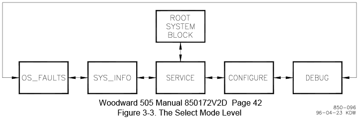
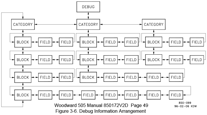
Refer to the [Generic
505 Debug Mode Overview] for instructions on entering the Debug Mode
and the Figures below illustrating the navigation arrangement
The Debug Tunable Blocks are in the S_MODBUS Category
There is an Individual Blocks dedicated to the DCS port and another block
dedicated to the HMI port
DCS.INIT_MOD for the DCS Port
HMI.INIT_MOD for the HMI Port
Both blocks contain fields that are twins for each other
The Tunable Fields for the Time Out and Network Address are:
DCS
Time Out Alarm Field: DCS.TIME_OUT or HMI.TIME_OUT
Network Address Field: DCS.NET_ADDR or HMI.TIME_OUT
(the Time Out Field Precedes the Network Address Field) when scrolling to the
right)
Both of the Fields are reached by moving laterally with the Diamond
Navigation Key from within the
DCS.INIT_MOD or the HMI.INIT_MOD Blocks which are nested under the S_MODBUS Category
Instructions / Generic to multiple 505 version
variations
Debug Mode Procedure Instructions / Generic to multiple 505 version
variations
Written 7/2012 / Updated 11/2012
- Summary / Generic to multiple versions of the 505 Governors
- Enter the Debug Mode Level (The Debug Mode Password is 1112)
- Then Scroll Laterally (Left or Right) to the specific Category
- Then Scroll Down to the desired Block
- Then Scroll Laterally again to a specific Field
- Change the Field Value as needed
- Navigation / Generic to multiple versions of the 505 Governors / Debug and
Service Modes
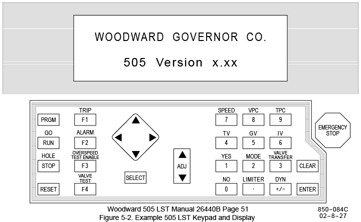
- The 505 Display has 2 lines that are sometimes independent. The
active line is marked with the @ symbol. The @ symbol can be moved up
or down with the SELECT Key
- Use the Diamond (4 Arrow) Navigation Key to Scroll up and down or left
and right
- To change values, use the ADJ Key or type in a value.
- To Type In a Specific Value, press the ENTER Key, type in a numeric
value with the Keypad including a decimal point if needed, then press the
Enter Key again to accept the value.
- Press the CLEAR Key to move back up a level in the Tree. Press
CLEAR again to exit the Debug or Service Mode
- Enter the Debug Mode (one of several methods) Generic to multiple versions
of the 505 Governors
The turbine and the 505 governor must be shutdown
- The Debug Mode can be accessed while the unit is running (noted 11/2012)
As with the Service Mode, you cannot make a large step change.
- Press the Clear Key once or twice to display the Root Block "WOODWARD
GOVERNOR CO."
- Scroll down one level to the Mode Level
- Scroll Laterally through the various Modes to the Debug Mode. The display should indicate
"Push ENTER for DEBUG"
- Press the ENTER Key.
- Enter the Debug Password 1112
- Press Enter to transfer the Password
- Another Variation to Enter the Debug Mode / Generic to multiple versions
of the 505 Governors
- Woodward Application Note 51346 Instructions (Tasker
Edit to focus on the Debug Mode) or (Unaltered
Original)
- Press the “PRGM” Button.
- This takes you directly to a repeatable location in the Mode Level, the
Program Mode.
- The text, “Password CONFIGURE”, will appear.
- Press the Right Arrow (>) key until the text, “Push ENTER for DEBUG”,
appears.
- Press the “ENTER” Button, enter the DEBUG password “1112”, and press the
“ENTER” Button.
Instructions / Specific the 505 LST Modbus Network Address and Communication
Time Out Alarm
Updated 9/11/12
- Note: menus are looped, so scrolling can be either direction, but the
directions specified below are the most direct route.
- From within the Debug Mode, scroll LEFT 9 steps to the Category Heading S_MODBUS
- Scroll UP from within the S_MODBUS Catergory
3 steps to reach the to the Block HMI.INIT_MOD block, or
4 steps to reach the to the Block DCS.INIT_MOD block
- To Change the Communication Time Out Value
- Scroll RIGHT 9 steps from within the either DCS.INIT_MOD or the
HMI.INIT_MOD Block to the field
DCS.TIME_OUT or HMI.TIME_OUT
- Press the ENTER Button, then use the Numeric Keypad to specify a
value. Press Enter again to accept the keyed value.
- The Default Value is 3 Seconds. The tunable range is 0 to 100
seconds. A Communication Failure Alarm will latch if successful
communication has not occurred within the Time Out Value. A
Communication Failure Alarm has no effect on the actual communication.
Pressing the Reset Key from within the alarm menu will clear the alarm latch. Some
applications may experience delayed communications for various reasons.
3 seconds is good starting point, but if excessive Communication Failure
Alarms are occurring, then try a larger number like 10 or 20 seconds.
- To Change the Modbus Device Address
- Scroll RIGHT one more field after the DCS.TIME_OUT or HMI.TIME_OUT
field,
or Scroll Right 10 steps from the beginning of the DCS.INIT_MOD or
DCS.INIT_MOD Block
to
the field DCS.NET_ADDR or HMI.NET_ADDR
- Use the ADJ Key to increment the integer value up or down to the
desired Device Address
- Scroll through the block fields to confirm the New Values have been
accepted.
- Press the Clear Key once to move back up to the Category level.
- Press the Clear Key again to exit the Debug Mode.